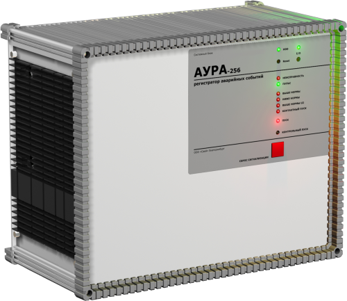
AURA-256
Conventional Digital Fault Recorder (DFR)
- quick replacement of individual modules
- 256 analog and 1024 binary channels
- modular design
The AURA recorder has a modular design allowing individual modules, particularly input transducers, to be replaced quickly. The number of recorded quantities can be expanded in service through additional hardware, and configuration settings can be changed. It measures and monitors equipment under normal operating and fault conditions at power utilities and industrial facilities. Cabinets can be fitted with forced ventilation and automatic heating for installation in unheated rooms.
Request a quoteDesign
The main unit has an aluminum-profile enclosure that provides electromagnetic shielding and the mechanical strength required for long-term industrial service.
- Modular design allows individual units, including input transducers, to be replaced quickly;
- The number of recorded parameters can be expanded by adding hardware during service;
- Configuration settings can be changed during service;
- Latched indication of recorder triggers;
- Latched indication of recorder faults;
- Relay contact output for trigger and fault indication;
- A test trigger can be used to check disturbance recording;
- Local and remote reset of trigger indications and fault alarms.
Configuration
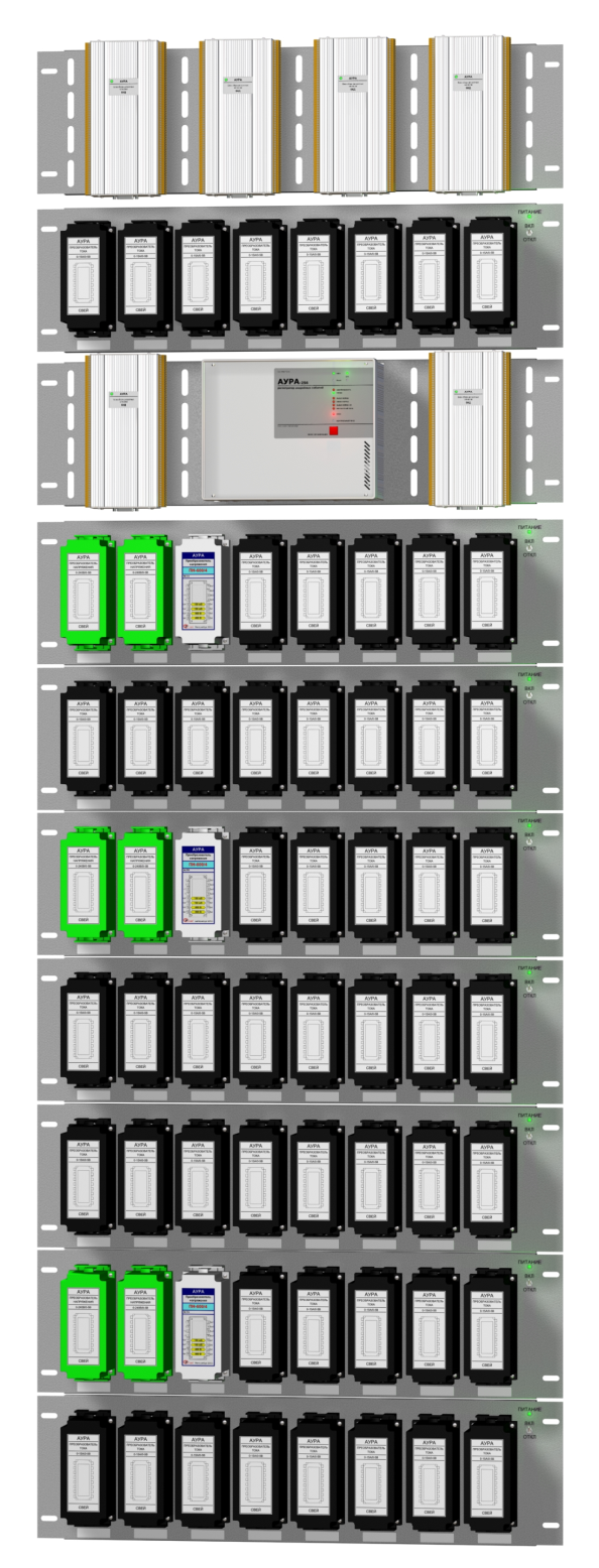
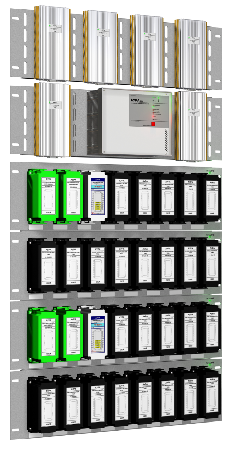
The AURA recording unit has eight connectors for 256 analog inputs and eight connectors for binary input units with 64 channels each. This version supports configurations with up to 256 analog and 512 binary channels.
AURA recorders can therefore be configured with any number of analog and binary channels within the limits stated above.
The input transducer configuration and number of binary acquisition modules are specified by the measurement channel list prepared when ordering.
Upgrades
The recorder's channel count can be expanded in service by installing additional input transducers and binary input modules. The software configuration is updated as required.
Equipment installation
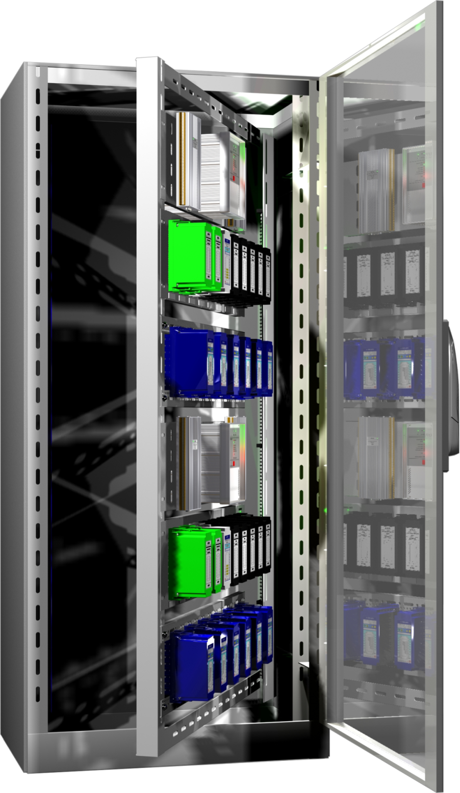
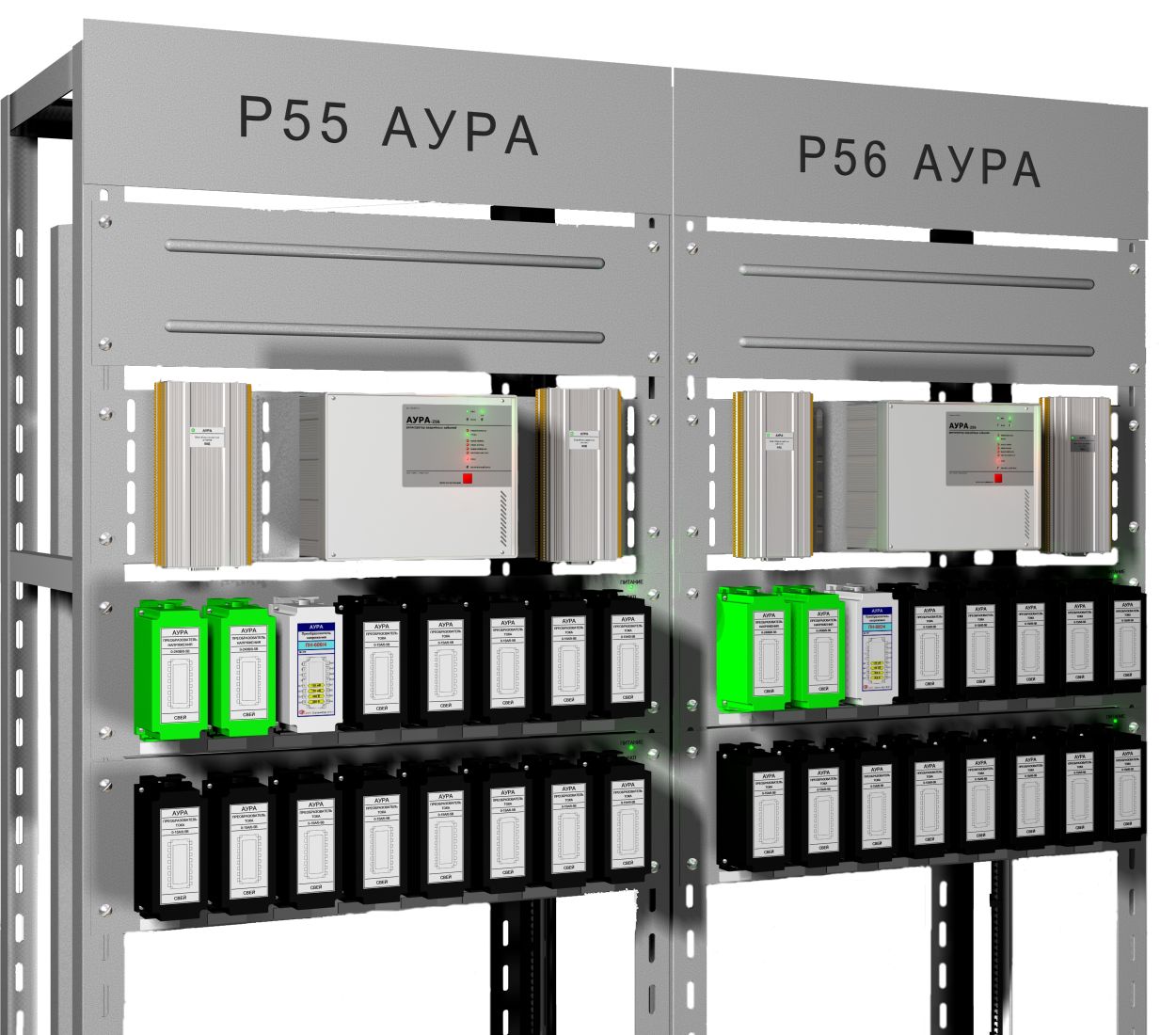
Recorders are supplied:- As individual modules for installation on existing panels
- As fully assembled panels with internal wiring completed
- In fully wired cabinets with front and rear access
- In cabinets with front access only, with equipment mounted on a swing frame.
Cabinets can be fitted with forced ventilation and automatic heating for installation in unheated rooms.
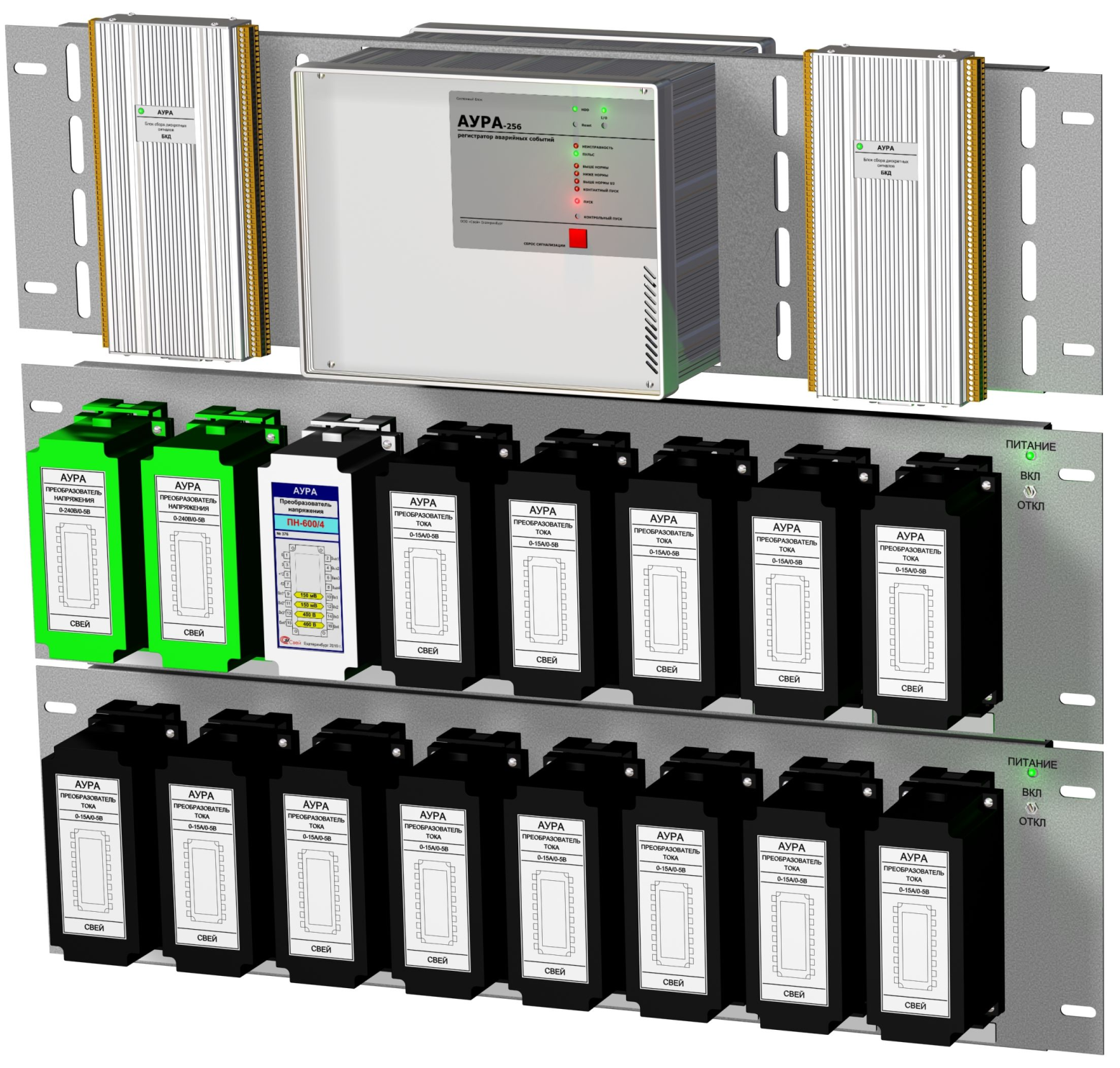
The BKD modules are shown beside the main unit for illustration of the equipment configuration.
Applications
The AURA digital fault recorder measures and monitors electrical quantities under normal operating and fault conditions in power and industrial facilities.
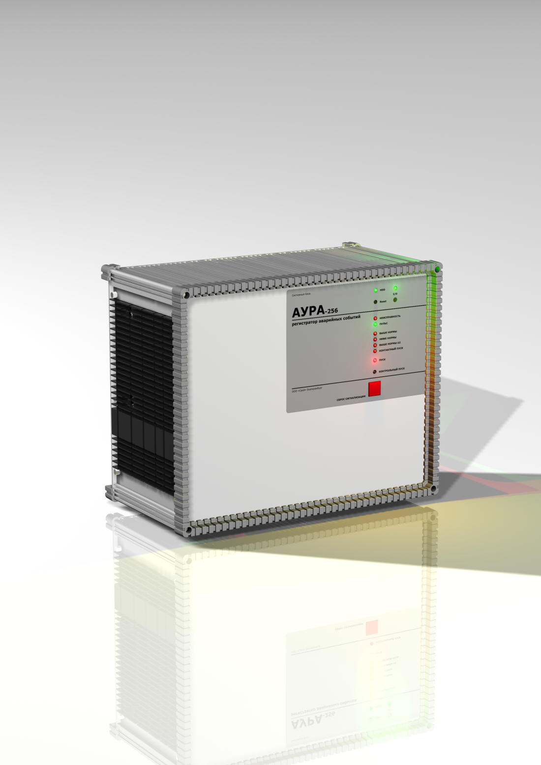
The AURA central unit has an industrial, vibration-resistant aluminum extrusion housing.
The main unit contains a fanless single-board computer, an interface unit with a 12-bit ADC, and analog and binary signal switching modules.
External communications use Ethernet at 10 Mbit/s or higher, USB ports and a serial port.
The recording unit has a fanless, dust-protected enclosure. It is powered by an external 12 V DC supply accepting 120–370 V DC or 85–264 V AC.
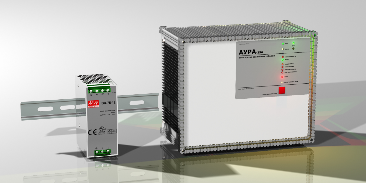
- LED indicators;
- recorder power, test trigger and alarm reset buttons.
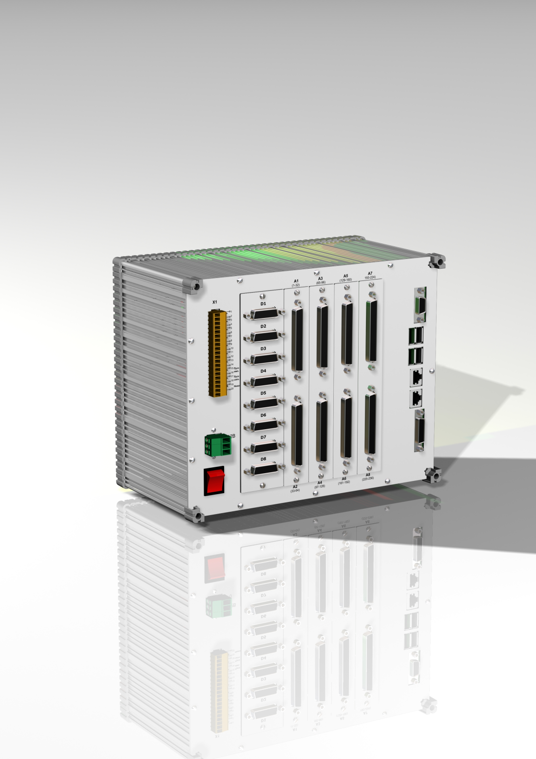
- up to eight binary input units (512 channels) and eight analog input transducer modules (256 channels). In recorders with fewer analog channels, blanking plates replace unused analog multiplexer units;
- the recorder power button;
- connector for the 12 V DC supply cable;
- terminal block for external alarm circuits;
- the processor board connection panel for external devices.
Windows XP Embedded or Linux operating system.
Input transducers
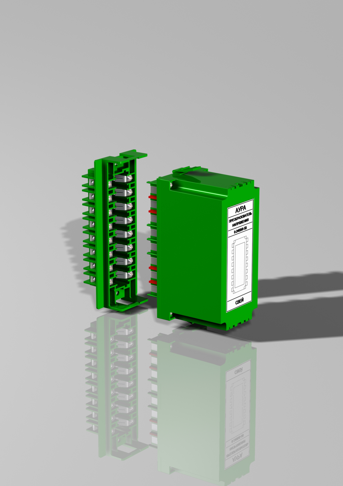
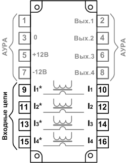
AURA transducers are housed in standardized plug-in plastic enclosures, with four channels per enclosure. The cover is secured to the connector section with four screws and has two latches that lock the transducer into its mating connector. The input connector is similar to a conventional BI-6 test block. It shorts the current circuits when a transducer is withdrawn and permits current-injection testing and insulation testing of the incoming cables. Guide ribs between the connector contacts prevent short circuits if the transducer is accidentally tilted during insertion. The mating connector has M4 screw terminals for the input and output circuits. Different transducer types use different enclosure colors, and their mating connectors are color-matched.
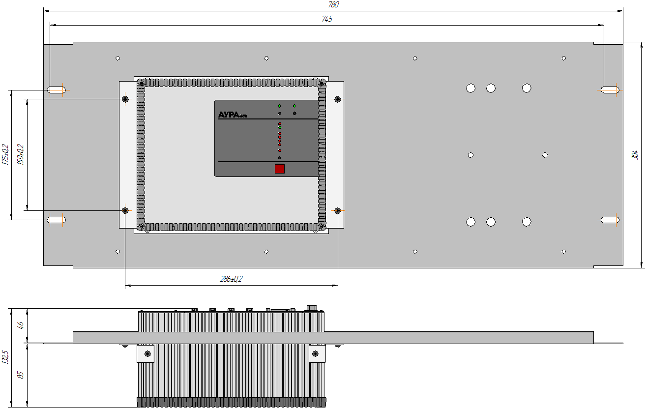
The transducers are grouped into modules with mounting provisions for a standard protection panel or cabinet. Modules can be installed up to 3 m from the main unit.
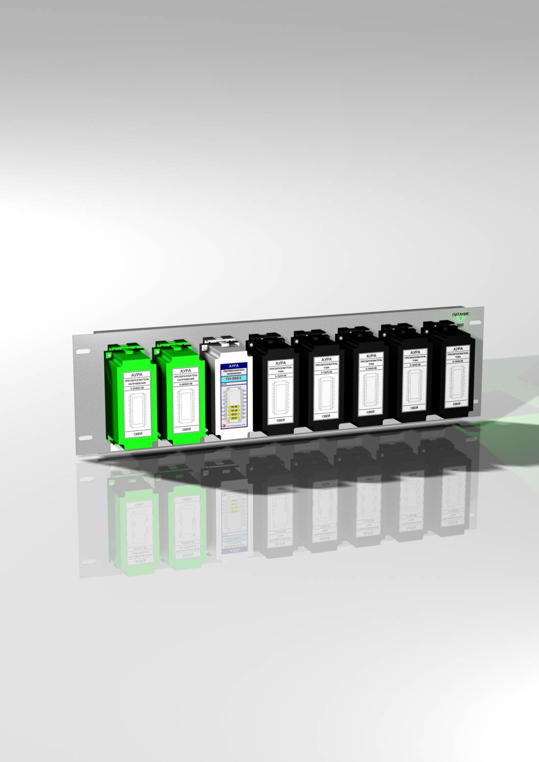
Each module accommodates up to eight input transducers in any order. The rear of the module carries a recorder connector and routing channels for input wiring harnesses. Modules have an LED indicator and a power switch.
Remote signals can be recorded using remote disturbance transducers of type SPT-100/20-4 with a 0–20 mA output or EP8527 with a 0–5 mA output.
For normal-operation measurements, electrical and physical quantity transducers with 0–5, 0–20 or 4–20 mA outputs are used, together with our digital transducers (SPC) or those from other manufacturers.
Input transducers with 0–5, 0–20 or 4–20 mA outputs and digital transducers can be distributed around the facility or installed in the input transducer modules. Resistor modules or galvanically isolated DC current transducers are provided for connecting and installing current-loop transducers within these modules.
BKD
The BKD binary input unit connects and galvanically isolates 64 volt-free contact channels. Its input terminal block accepts cable conductors up to 2.5 mm² in version 1 and up to 1 mm² in version 2; 1 mm² shielded control cable is normally used. A 15-pin output connector connects the unit to the recorder. A green LED indicates power. The input circuits are supplied by a built-in isolated 30 V source. The BKD itself receives power from the AURA recording unit through its connecting cable. BKD units are normally mounted on the terminal side panels of panels or cabinets with front and rear access, or on the rear wall of cabinets with front access only. The maximum distance from the recording unit is 3 m.
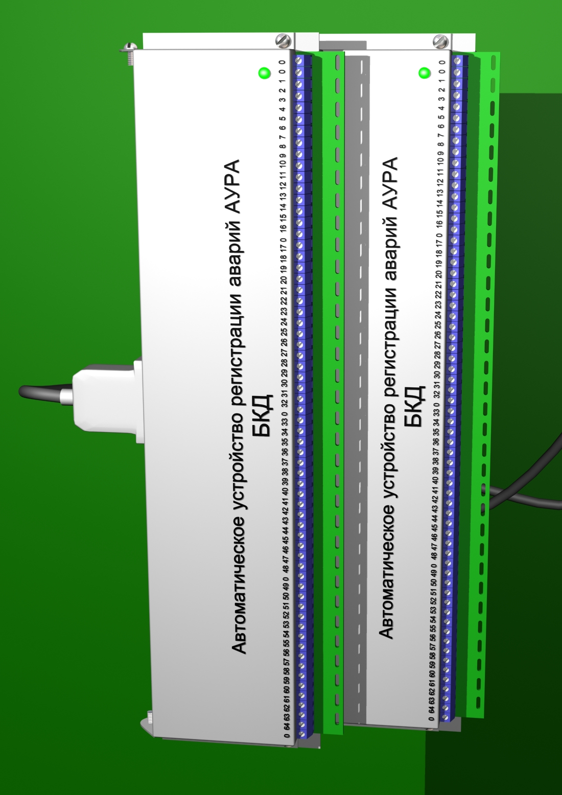
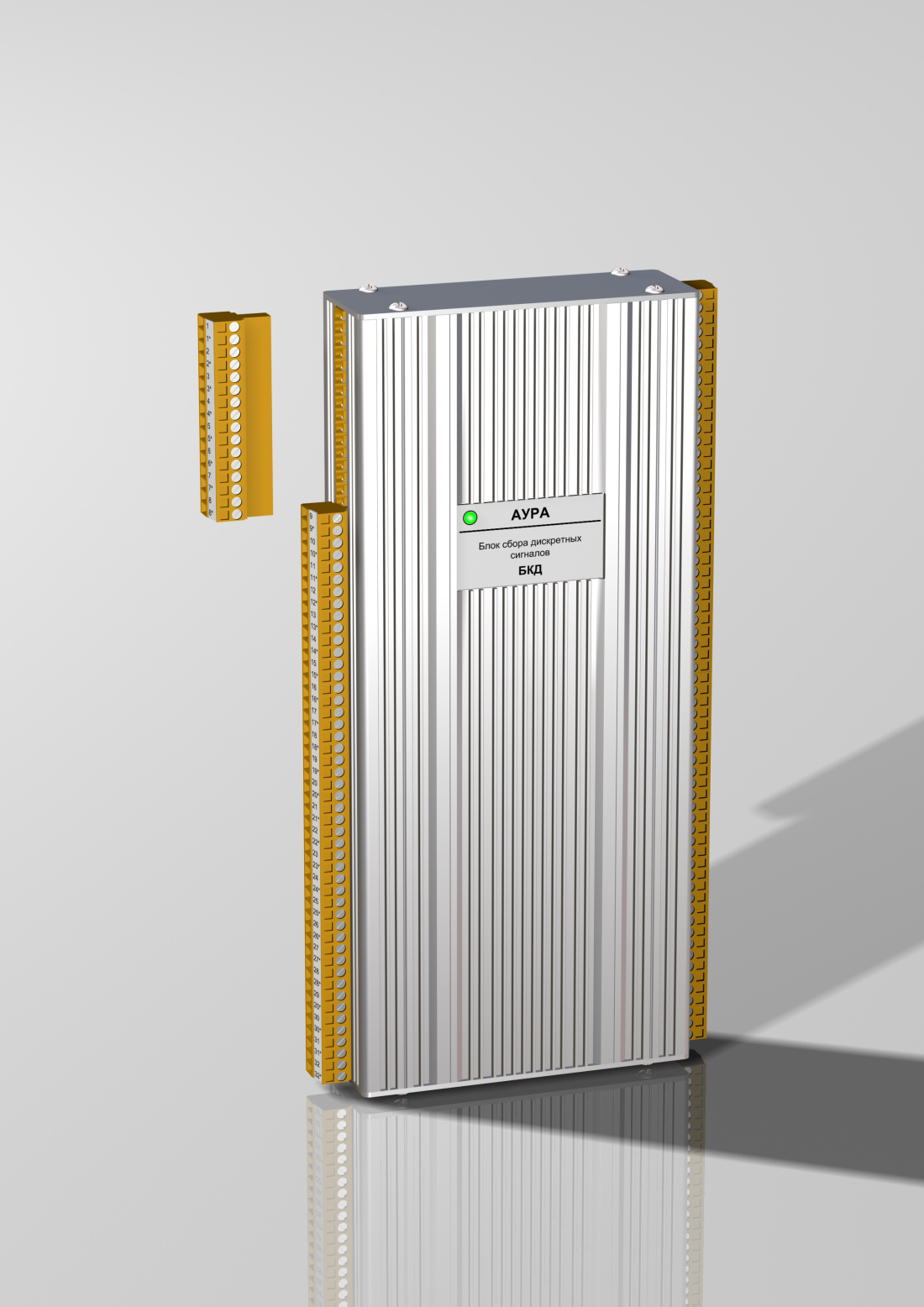
BKD-64 versions 1 and 2 provide the same functions. They differ in mechanical design and the number of common terminals. Version 2 has cable connections on both sides. Version 1 has six common terminals marked [0], while version 2 has 64 marked [1*–64*]. Because version 2 requires access from both sides of the unit, it can be installed only in a cabinet serviced from the front. Cabinets serviced from both front and rear use version 1 only. Where additional common terminals are required, extra terminals are fitted above the BKD. An example connection to version 1 is shown in technical documentation section. The common channel conductors can be joined at the connection point or at intermediate panels and connected to the BKD module using a single conductor.
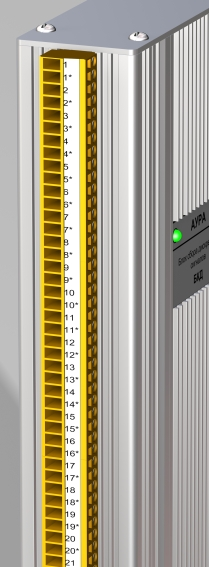
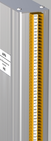
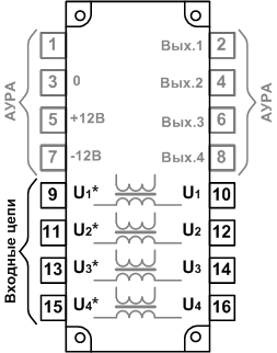
BKD version 2 connector numbering
Terminal numbering starts at the upper-left terminal. Two terminals are allocated to each signal. Preferably, use a separate twisted pair in a shielded telephone cable for each signal.
BKA board types used in AURA-256, AURA-128 and AURA-64 recorders
Three types of analog multiplexer boards have been used in AURA-256, AURA-128 and AURA-64 recorders:
1. AOUT64
64-input switching module.
Manufactured through 2009.
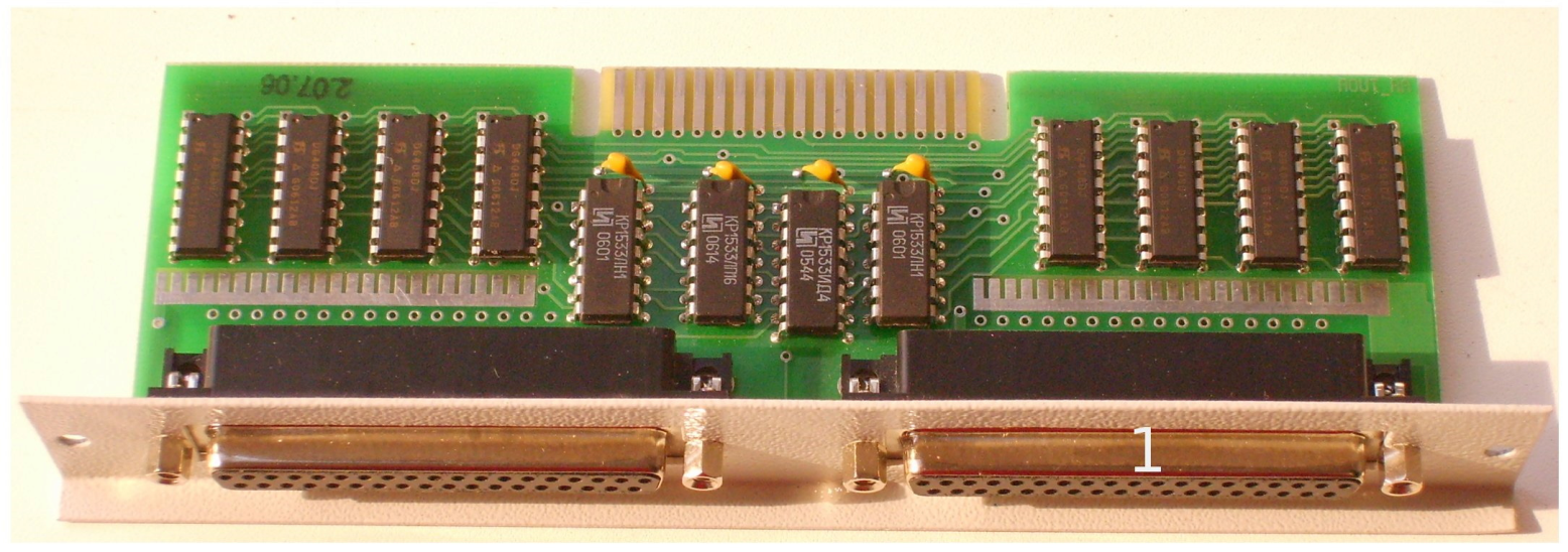
Used in AURA recorder models with separate concentrators in steel enclosures, and in aluminum extrusion enclosures with Mini-ITX processor boards: EPIA ML5000, EPIA V5000, EPIA ME6000, EPIA LN10000 or NEX620.
2. BKA_2.1 (part number SVE.01.1107.250)
32-input multiplexer board.
Manufactured from November 11, 2009 to November 20, 2014.
The 64-input BKA_2.1 multiplexer assembly consists of two BKA_2.1 boards mounted on an aluminum rail.
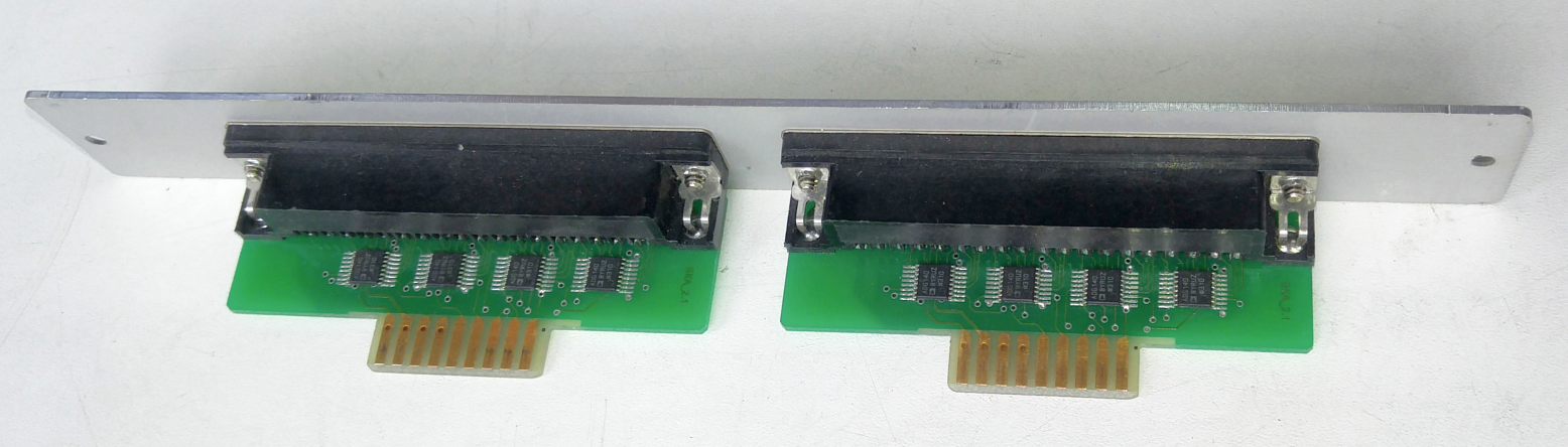
To purchase a BKA_2.1 module, order two BKA_2.1 boards (part no. SVE.01.1107.250) and one mounting strip (part no. SVE.01.1107.000.01).
3. BKA_3.1 (part number SVE.01.11.09.250)
32-input multiplexer board.
Manufactured since December 23, 2014.
The 64-input BKA_3.1 multiplexer assembly consists of two BKA_3.1 boards mounted on an aluminum panel.
Used in AURA recorders with aluminum extrusion enclosures and an MS-98D1 processor board.
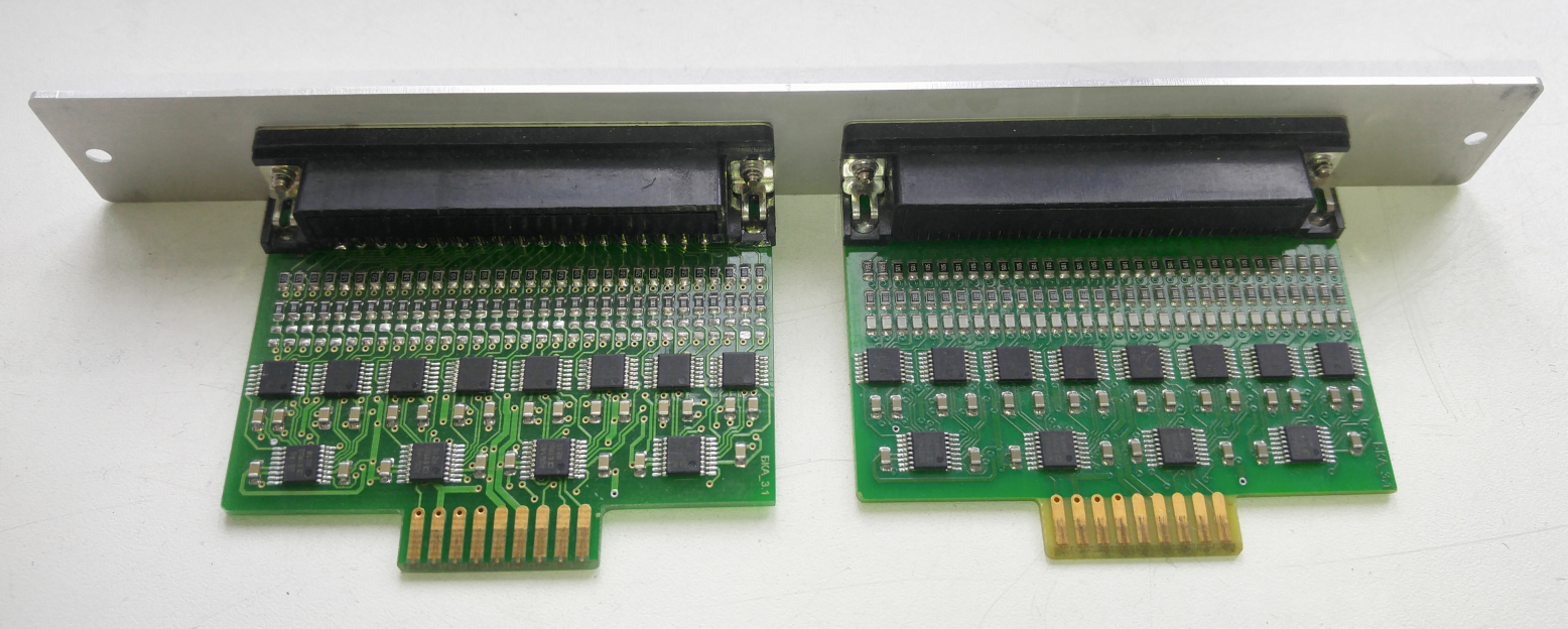
- BKA panel marked “A1,A2” (part number SVE.01.1109.000.02)
- BKA panel labeled “A3,A4” (part no. SVE.01.1109.000.02-01)
- BKA panel marked “A5,A6” (part number SVE.01.1109.000.02-02)
- BKA panel labeled “A7,A8” (part no. SVE.01.1109.000.02-03)
To purchase a BKA_3.1 unit, order two BKA_3.1 boards and one panel.
Note
The manufacture dates of BKA boards may differ from those of the AURA recording units in which they are fitted. Recorders manufactured from 2016 onward use BKA_3.1 boards. For earlier recorders, compare the fitted boards with the photographs shown.| Number of analog channels | Number of binary channels | Samples per cycle (scanning rate, Hz) |
|---|---|---|
| 2 | 8 | 20…1536 (1000…76800) |
| 4 | 16 | 20…768 (1000…38400) |
| 8 | 32 | 20…384 (1000…19200) |
| 16 | 64 | 20…192 (1000…9600) |
| 32 | 128 | 20…96 (1000…4800) |
| 64 | 256 | 20…48 (1000…2400) |
| 128 | 512 | 20…24 (1000…1200) |
| 256 | 1024 | 20 (1000) |
- ADC resolution 12 bits
- Triggers: any analog or binary channel, calculated U2(I2) and 3U0(3I0)
- Maximum disk usage during disturbance recording 300 KB/s
- Cabinet supply 220/110 V DC, 220/127 V AC
- Binary alarm output specifications:
- Switching voltage up to 400 V
- Switching current up to 50 mA
- Processor clock speed at least 800 MHz
- RAM at least 1 GB
- Storage at least 8 GB flash or an 80 GB hard drive
- Communications: Ethernet at 10 Mbit/s or higher, remote modem access, Bluetooth, Wi-Fi
-
Disturbance file size, kB: Lfault = Nchannels * 2 * Fsample × Trecord / 1024, where
- Nchannels – number of recorder channels
- Fsample is the sampling rate, Hz
- Trecord is the recording duration, s
- Operating temperature range: +1 to +45 °C
The recorder meets GOST 22261-94, GOST R 50377-92 for safety, and GOST R 50839-95 (Group 2) and GOST R 51318.22 (Class B) for electromagnetic compatibility.
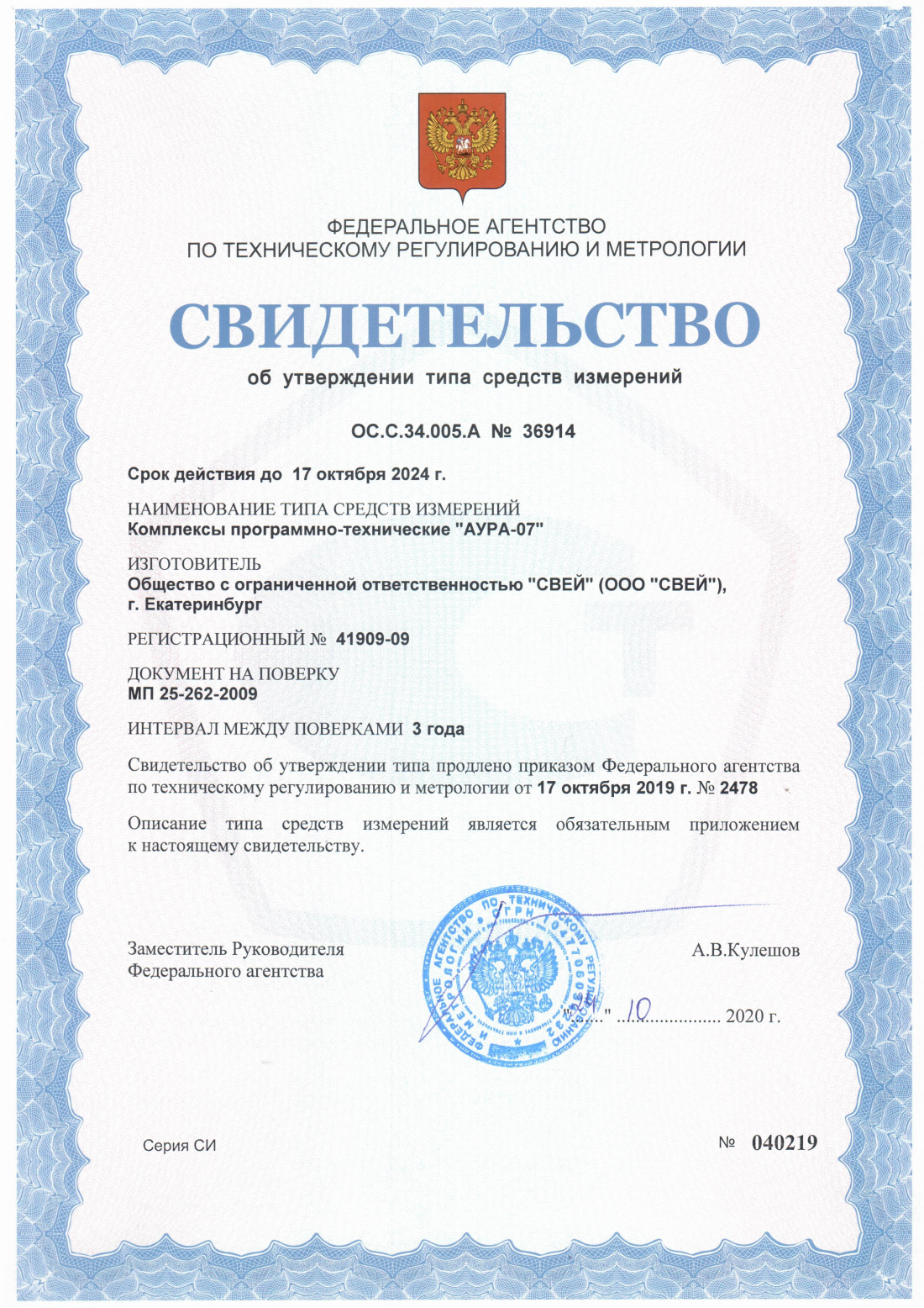
The AURA-07 hardware and software system is listed in the Russian State Register of Measuring Instruments, registration no. 41909-09.
Accuracy class:
AC current and voltage: 0.5
DC current and voltage — 0.5
phase displacement: 0.5
frequency — 0.05
Weight: 2.6 kg.
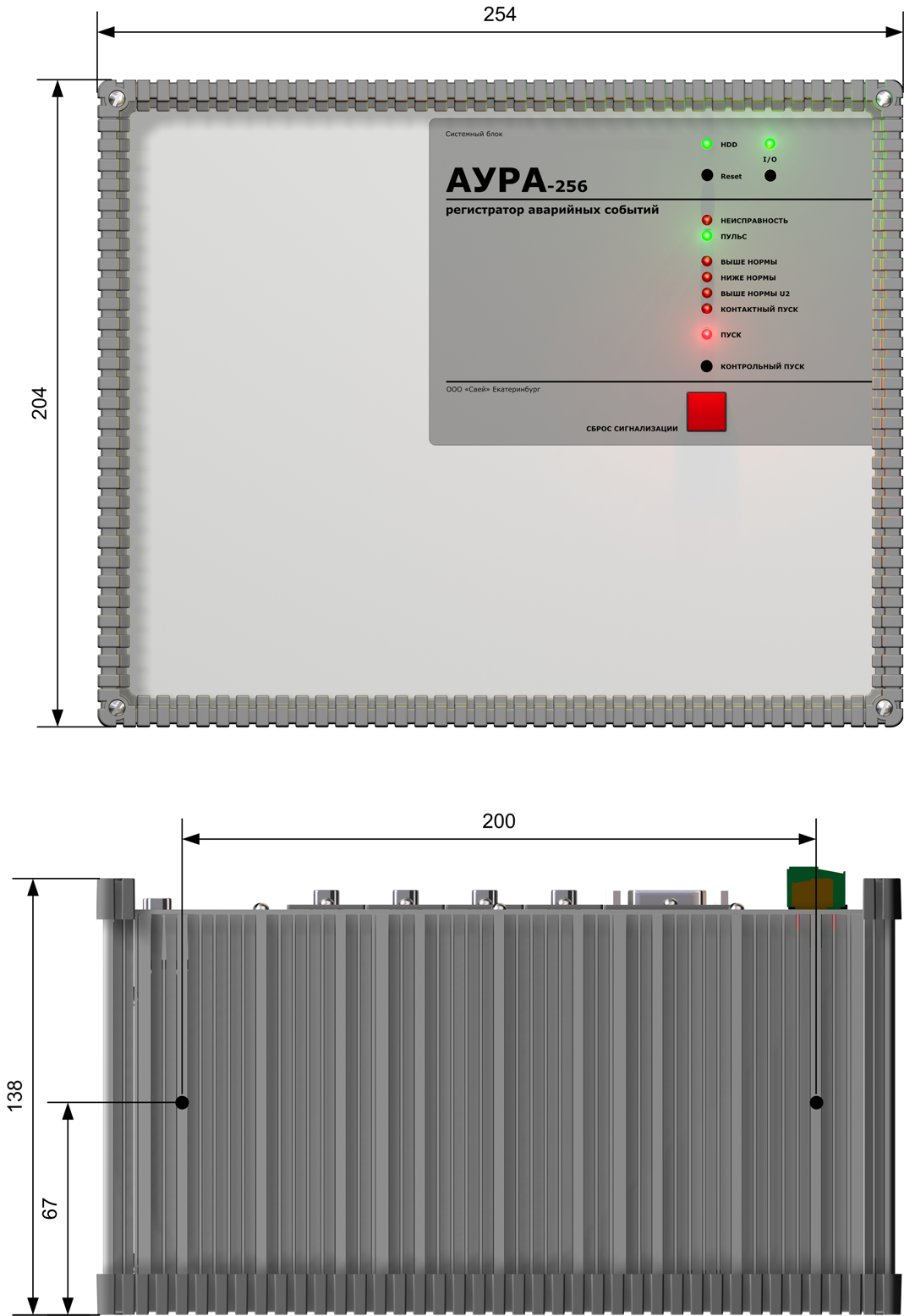
Weight 6.7 kg.
- Measurement error no greater than 0.5%;
- Galvanic isolation voltage: 3000 V;
- Input impedance at 50 Hz:
- AC current transducers: 0.0075 Ω;
- AC voltage transducers: 2 kΩ;
- DC voltage transducer input current — 0.5 mA.
| Transducer type | Measurement range and unit | |||
|---|---|---|---|---|
| AC voltage transducer | 80 V | 120 V | 160 V | 240 V |
| DC voltage transducer | 150 mV | 200 V | 400 V | 600 V |
| 0–3 A AC current transducer | 1 A | 1.5 A | 2 A | 3 A |
| 0–15 A AC current transducer | 5 A | 7.5 A | 10 A | 15 A |
| 0–60 A AC current transducer | 20 A | 30 A | 40 A | 60 A |
| 0–180 A AC current transducer | 60 A | 90 A | 120 A | 180 A |
Weight: 0.9 kg.
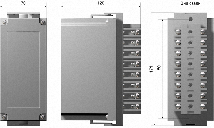
Weight: 9.2 kg.
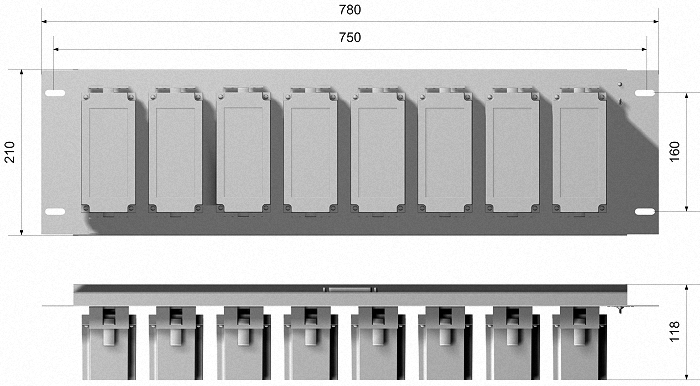
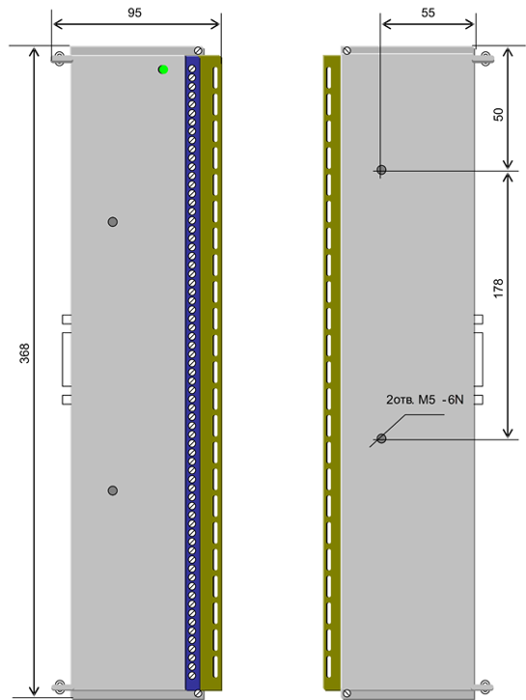
Weight 1 kg.
Weight 0.7 kg.
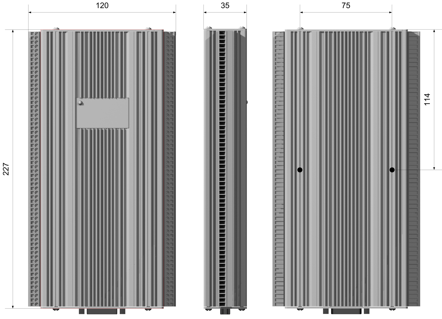
- Disturbance recording, generating an AURA-format file or files in both AURA and COMTRADE formats;
- automatic processing of disturbance files, including a text report with disturbance analysis and fault location, and a time-limited extract containing the signals that changed during the disturbance;
- recording binary state changes by creating files listing the binary channels that changed state during the day;
- normal-condition recording: measurement files for normal operating channels, sampled every 5–180 seconds and retained for seven days;
- emailing newly recorded files and diagnostic messages, including over a dial-up modem connection;
- transferring newly recorded files to specified locations on the Ethernet network;
- transferring newly recorded files over IEC 60870-5-104;
- a web server for access to data through Internet Explorer;
- automatic copying of disturbance files to a USB flash drive when one is detected;
- network access over a dial-up modem connection;
- time synchronization:
- Network Time Protocol (NTP) client;
- support for multiple time servers;
- synchronization to satellite navigation signals;
- self-diagnostics with status indication and event logging, including input transducer diagnostics;
- in the IEC 61850 version, receipt of binary status information using IEC 61850 GOOSE.
Data storage and transfer
Disturbance files are stored on the recorder's drive, in the AWR and COMTRADE folders, until deleted.
Files can be deleted in the following ways.- manually;
- automatically after a new recording, by deleting the oldest file when disk usage reaches 80%;
- On a large drive, the number of files can reach several thousand, making them harder to manage. The recorder allows a maximum file count to be set. When a new recording exceeds this limit, the oldest excess file is deleted automatically.
- By copying files from the recorder over Ethernet through Windows Network. Recorder access must be configured at the share or user level;
- downloading files directly through the web interface while access to the recorder's shared resources is disabled. Internet Explorer is used for this method. The web interface home page is password-protected;
- copying to laptops, handheld computers and mobile phones over Bluetooth or Wi-Fi. This requires a wireless access point or an optional wireless adapter installed in the recorder;
- By copying files directly from the recorder to a USB flash drive. When a drive is inserted into the USB port, recent disturbance files that have not yet been copied are copied automatically, together with a transfer report.
- downloading files directly over Ethernet, including remote access through telephone modems;
- downloading files directly through the web interface;
- automatically emailing data to specified addresses through a mail server. The recorder can automatically establish a dial-up modem connection to a configured number;
- transmission of disturbance records as measured values using IEC 60870-5-104.
Measurements under normal operating conditions are available through IEC 60870-5-104 and an OPC server.
-
НСОПБ ЮАБ0.RU.ЭО.ПР.316.Н.00020 No. 32828 637 KB
-
EAEU No. RU D-RU.RA01.V.71292/19 471 KB
-
OS.S.34.005.A No. 36914 2.19 MB
-
Operating manual
12.03.2020РЭ 4252-001-12325925-2016 4.62 MB -
Operator manual
12.03.2020РО 4252-001-12325925-2016 6.25 MB -
AURA order specification form
10.06.2008186 KB